|
There are four electrical components that interface with the PC/104 computer. These are the potentiometer, the key pad, the hall sensor, and the motor and power amplifier circuit. The potentiometer serves as a resistance level selector with a knob indicating increasing and decreasing resistance. It is provided 5 Volts from the PC/104 and the variable voltage chosen using the wiper is input back to the PC/104 as a force multiplyer. The other three components are described in more detail below.
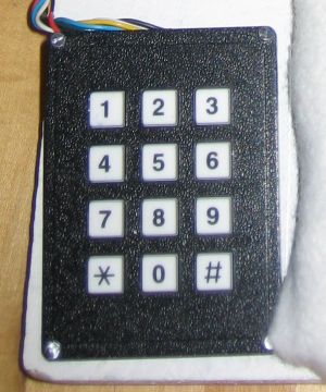
Keypad
The keypad is a standard 12 keys (0-9, *, and #). The first row, 1-3, selects the various program modes (1 for continuous, 2 for a three second delay between repetitions, and 3 for a random time delay between repetitions). The second row (4-6) is for the time duration, 1, 5, and 20 minutes respectively. The * is to start the training session and # is to stop the training session.
Each row is provided with a different voltage from the PC/104 analog outputs, 1 Volt, 2 Volts, and 3 Volts on pins 1, 2, and 4 (the third row is not used). Each column has an output with a 300 kOhm pulldown resistor (pins 5, 6, and 7). When a button is pressed, that column will read the corresponding row voltage.
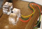
Hall Sensor
A Hall sensor is used to record the position of the paddle. By time-stamping this data, the PC/104 is able to calculate the velocity and give feedback to the user. The Hall sensor has an angular range of 70 degrees with only a portion used for this project.
For effective use of the hall sensor it has to be calibrated. The sensor was fit to a second order polynomial with the dependent variable being the angle of the paddle and the independent variable being the voltage signal from the sensor. In order to calibrate the model the voltage has to be measured at 35 degrees to the left of center, center, and 35 degrees to the right of center. These values can be put into MatLab in the following form:
Y = [-35, 0, 35]
X = [V1, V2, V3]
Then the coefficients to the second order polynomial can be found with the following command:
P = polyfit(X,Y,2)
These values can be used in the Simulink model to find the angle of the paddle from the Hall sensor.
Motor Amplifier
The haptic paddle used required a current amp to take a low current voltage input and output a high current to the motor. The input voltage selects the ouput current, so the circuit is able to control the torque of the motor. The diagram below shows the amplifier used. It includes a push-pull amp with transistors and uses an op-amp to assist in controlling the current through the motor.

Two heat sinks were installed with the transistors to prevent them from burning out.
|